How to draw SCD (System Control Diagrams) with Norsok I-005 / IEC PAS 63131
Introduction
System Control Diagram (SCD) is a method for design and documentation of safety automation and control systems.
The SCD concept returns to the basis of the P&ID, the process schematic. Information not required for the design of the control system is removed. The SCD focuses on representing systems and functional relationships, not individual physical equipment. SCD approach is commonly used in Norwegian oil&gas sector.
To illustrate usage of SCD approach, in this article we will describe simplified design of SCD for Wet Gas Cooler.
Wet Gas Cooler SCD creation example
In this example we will design SCD for wet gas cooler. The purpose of this subsystem is to cool the gas from the inlet separator to 30°C and pass it to wet gas scrubber. PCS, PSD, and ESD parts will be implemented.
PCS (Process Control System) will control cooling medium flow to maintain needed temperature.
PSD (Process Shutdown) part will monitor cooler outlet temperature and will shut down the process if temperature is high or low (HH and LL alarms).
ESD (Emergency Shutdown) part will be used for system shutdown and blowdown in case of ESD alarm.
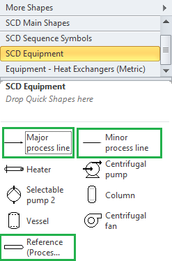
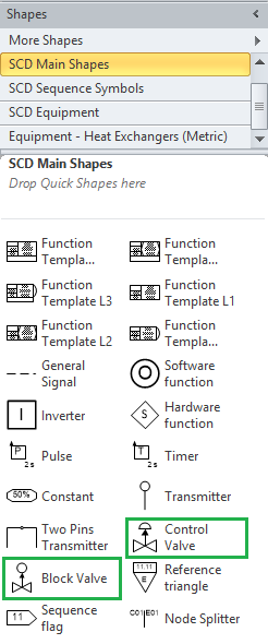
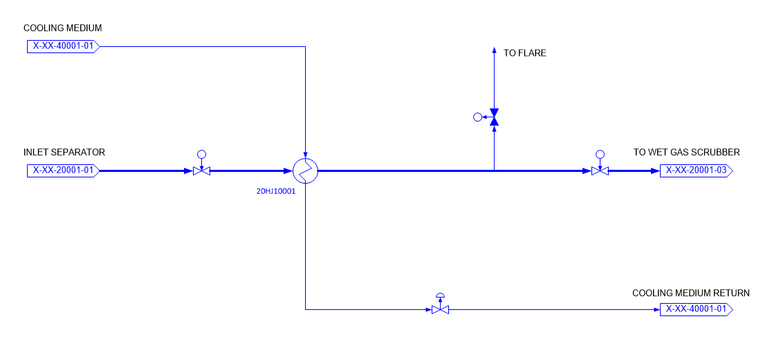
To begin with, we need to draw process equipment. For this purpose we will use SCD Visio Toolbox Equipment and Main Shapes stencils:
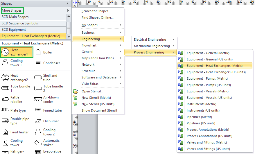
We also need Heat Exchanger shape. MS Visio contains significant amount of generic shapes, which could be used in combination with SCD specific shapes, provided with SCD Visio Toolbox. Heat exchanger could be found in Process Engineering stencil collection:
In order to make article more straightforward, we are not adding any control structures in this step, but actually next steps could be combined and you will likely put function blocks alongside with equipment.
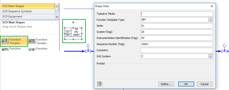
Main concept of SCD diagrams is Function Template. It is PLC function block representation for SCD. Complex control mechanisms could be implemented by interconnecting function blocks. There are different types of functional templates described in Norsok I-005. At this point we need blocks to control valves. SBV template is intended for block (open/close) valve control. When we put function template from stencil to diagram, we can select needed template type (SBV) and enter additional information, such as Tag and Node:
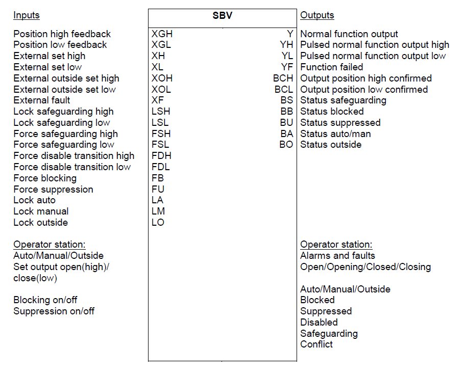
Next step is to make connection from block to valve. Each template in Norsok I-005 has possible terminal values. Illustration from Norsok I-005 for SBV template:
We will use Y output to make connection to valve. General Signal shape from Main Shapes stencil is used to make logic connections. When we connect signal to function template, terminal selection dialog appears:
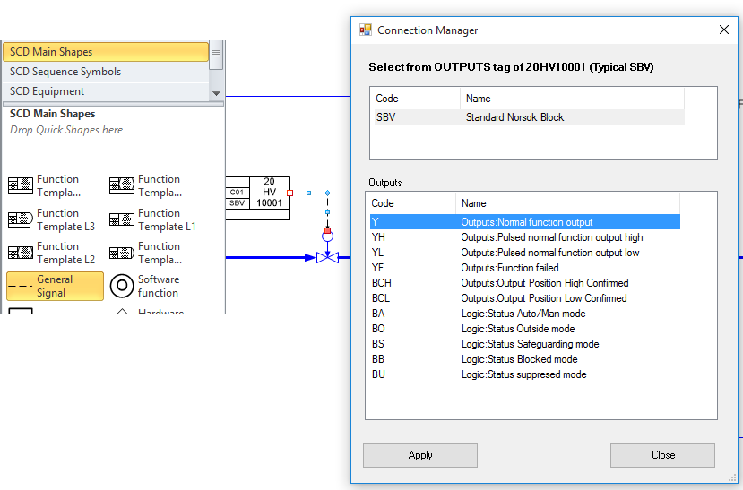
In our case we select Y terminal. Inlet valve control block is in PCS node, blowdown valve in ESD node and outlet valve in PSD node. When we select needed node in properties for function template, it is colorized accordingly. Connections, made to such blocks, are automatically transferred to needed node.
To maintain needed temperature we will use temperature transmitter on main process line and control valve on cooling medium line. For PID control Norsok I-005 “CA” block is used. This block will be in PCS node.
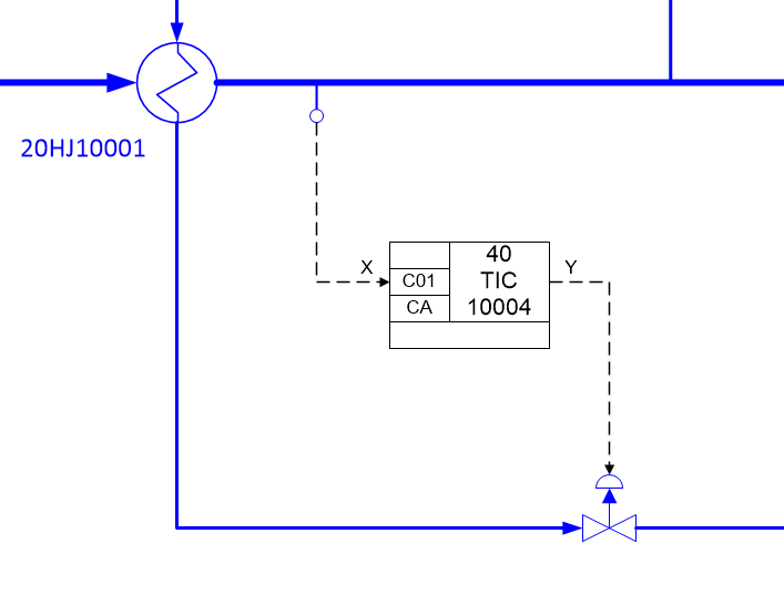
CA block is connected directly to transmitter and valve. If we need additional alarms (HH, LL) from transmitter, we should use additional MA block:
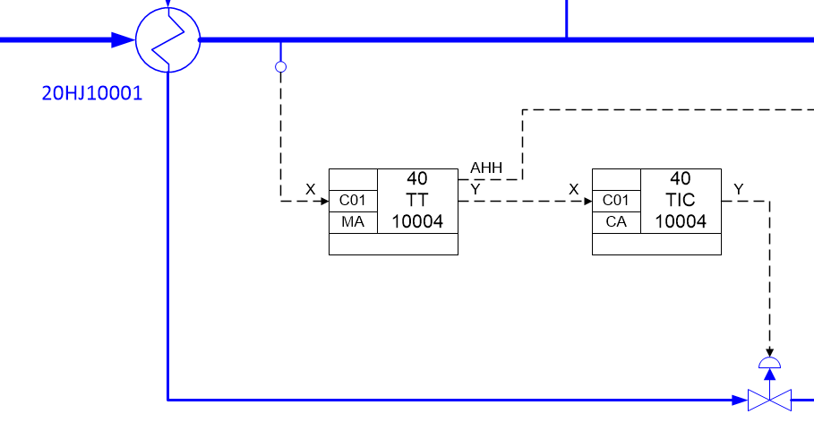
MA block is intended for monitoring of analogue value and has AHH and ALL outputs (Alarm High High and Alarm Low Low). In our case we will use separate transmitter for safety purposes and will not need MA block for 40TT10004 transmitter. 40TST10005 transmitter will be used to monitor temperature and close outlet in case of HH and LL alarms:
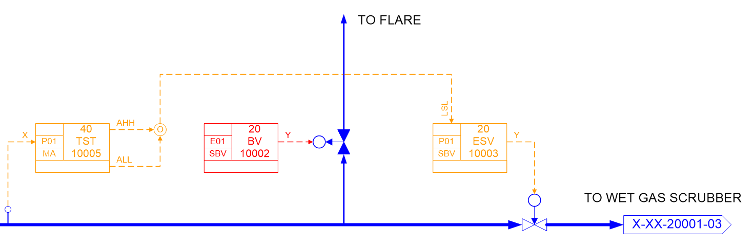
AHH and ALL outputs of MA block are combined with OR function (Software Function shape from Main Shapes stencil, provided with SCD Visio Toolbox). Combined signal is connected to LSL (Lock safeguarding low) input of SBV block. This input is intended for valve safeguarding. In case of HH or LL temperature, valve will be locked in manual mode and closed. According functional specification for this example, we also need to close 20ESV10003 in case of ESD 1.0 level activation. For this purpose we will use Reference Triangle (Main Shapes stencil) for ESD signal:
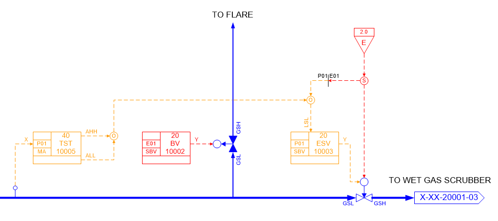
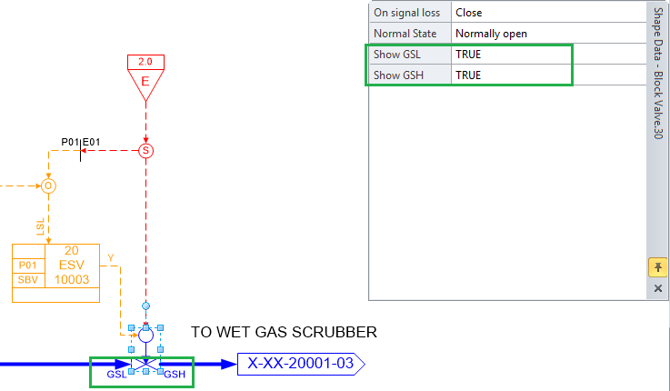
Signal from ESD is split into 2 signals. One is transferred to PSD node (Node Splitter shape could be used to indicate interconnections between nodes) and safeguards SBV block. Second signal is connected directly to its own ESD solenoid on valve. Safeguarding of SBV block is needed not only for redundancy, but to prevent unnecessary alarms, when SBV block is set to open position, but valve is closed due to ESD solenoid. Feedback signals from valve to SBV block are not routed explicitly on SCD diagram, but indicated by GSL/GSH symbols. In SCD Visio Toolbox you need to set Show GSL/Show GSH properties for valve to show those symbols:
While ESD 2.0 needs to close outlet valve, ESD 1.0 level activation should initiate blowdown. 20BV10002 valve is intended for this purpose.
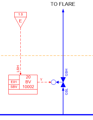
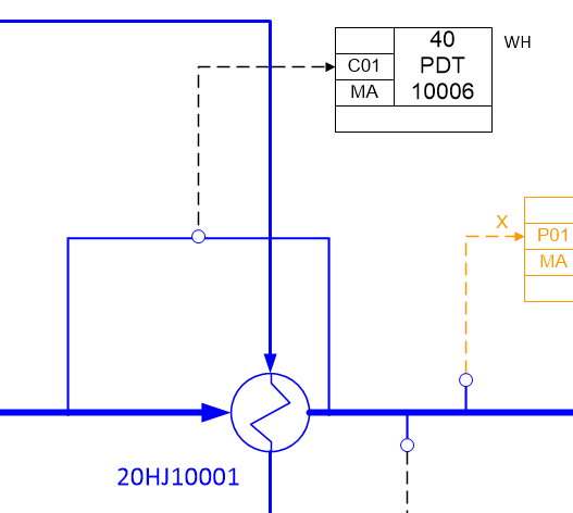
We connect ESD 1.0 signal to LSH (Lock safeguarding high) input, because we need to open blowdown valve in case of ESD initiation (valve’s failsafe position is open, it is indicated by arrow in valve’s symbol). You can explicitly indicate, that actual output signal is normally energized and valve will open on signal loss by using double arrow on signal to valve. Last thing we want to demonstrate in this article is adding of pressure difference transmitter. It will be used to monitor pressure difference between inlet and outlet of heat exchanger and indicate fouling of heat exchanger. We will not use any action alarms in case of high pressure difference, but we need to activate warning alarm. “WH” text near function block on SCD represents warning alarm High.
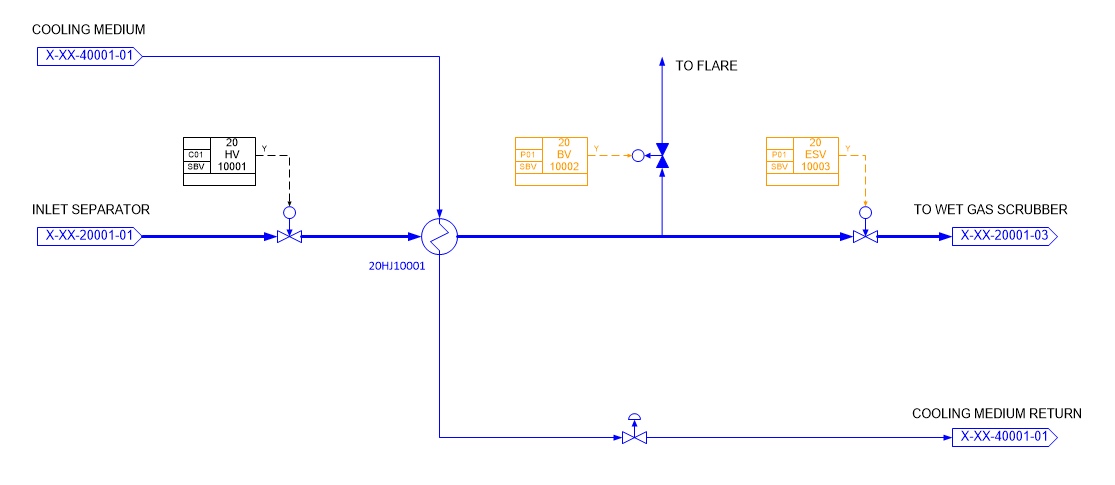
Final view of designed SCD:
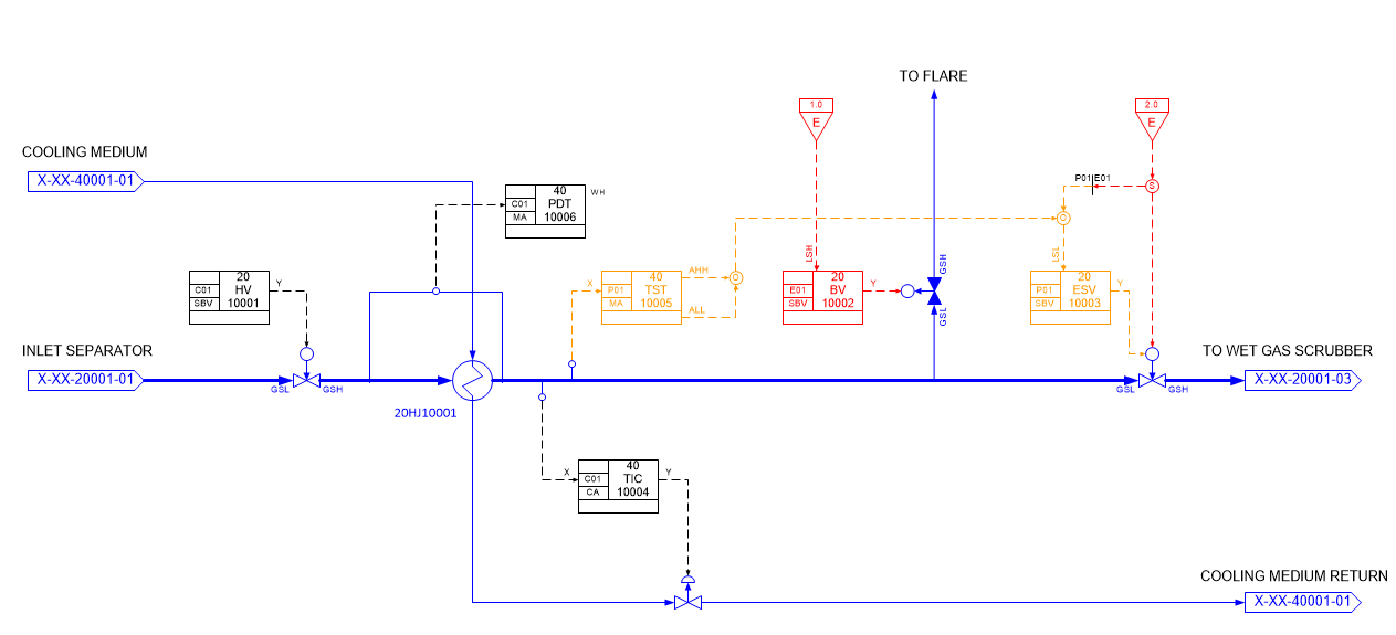
Note, that it is only example of SCD design and actual control structure for this subsystem was simplified for article clarity. Real wet gas cooling system will contain more instruments and control structures to assure safe operation.